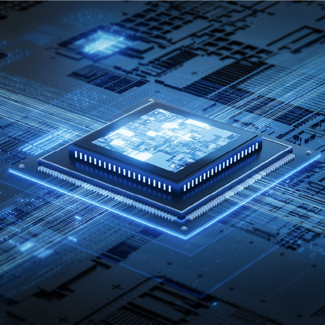
How advanced packaging is becoming the foundation of AI

For a long time, progress in computing followed a fairly predictable path. Shrink the transistor, get more density, keep power under control, repeat. Dennard scaling made that possible, and for decades it shaped how we thought about performance: more transistors meant more compute, almost by default.
That model has been breaking down for a while now, but the cracks have become impossible to ignore in the sub-5nm era. Leakage currents are no longer negligible; quantum effects are no longer theoretical edge cases, and power density is now one of the main constraints in any high-performance design. You can still push frequency and density, but the cost, in terms of energy and thermal management, rises disproportionately.
At the same time, workloads have changed in a way that makes these limits even more painful. Generative AI, large language models, and modern training/inference pipelines are not just compute-hungry, they are bandwidth-hungry. Moving data efficiently has become at least as important as processing it. In many real systems, it is the dominant factor.
This is the context in which advanced packaging has moved from a back-end concern to a central architectural lever.
From monolithic dies to disaggregated systems
One of the most visible shifts is the move away from monolithic chips toward disaggregated architectures built around chiplets.
There are very practical reasons for this. As die size increases, yield drops nonlinearly. When you approach the reticle limit of EUV lithography, even a small defect density translates into a significant number of unusable dies. At some point, making a single large chip simply stops being economically viable.
Disaggregation offers a way out. Instead of forcing everything onto one piece of silicon, functionality is split across multiple dies, each optimized independently:
- Compute-heavy blocks can use the most advanced nodes available
- Analog, I/O, and memory interfaces can stay on more mature, cost-effective processes
- Different IP blocks can be developed, validated, and even sourced separately
Of course, this only works if the pieces can communicate as if they were still part of a single chip. That requirement has driven the development of high-speed die-to-die interconnect standards such as UCIe.
What matters here is not just raw bandwidth, but latency and energy efficiency. If moving data between chiplets costs too much, in time or in picojoules per bit, you lose most of the benefits of disaggregation. The goal is to make that boundary almost invisible from a system perspective.
2.5D integration and the rise of the interposer
Before true 3D stacking became practical at scale, 2.5D integration emerged as a very effective compromise. Instead of stacking dies, it places them side by side on a shared silicon interposer.
The interposer is often described as “just wiring,” but in practice it is a highly engineered structure. It enables interconnect densities that are simply not achievable on organic substrates, while avoiding some of the thermal and manufacturing challenges of full 3D integration.
This approach has become the standard in high-end AI accelerators, largely because it enables tight integration with HBM.
High Bandwidth Memory changes the memory hierarchy quite dramatically. By stacking DRAM dies vertically and placing the stack close to the compute logic, you can achieve enormous bandwidth, far beyond what traditional DIMM-based systems can provide. The interposer acts as the bridge, routing thousands of signals between compute and memory with very fine pitch.
But this density comes at a price. At these speeds and geometries, signal integrity is no longer a secondary concern. Crosstalk, impedance discontinuities, and electromagnetic coupling all must be carefully managed. The interposer design starts to look less like a routing problem and more like a high-frequency analog design challenge.
Moving to 3D: density vs. reality
If 2.5D is about proximity, 3D integration is about density.
Stacking dies vertically reduces interconnect length even further and opens up new architectural possibilities. In principle, you can bring memory and logic so close together that the boundary between them almost disappears.
The traditional way to connect stacked dies is through micro-bumps. These are small, but not small enough to keep scaling indefinitely. There is a practical limit to how tight the pitch can be, and that limit becomes a bottleneck.
Hybrid bonding is one of the key technologies pushing past that limit. By eliminating solder bumps and directly bonding copper pads between wafers, it enables much finer interconnect pitch and significantly higher connection density.
The impact is not just geometric. Shorter, denser interconnects mean lower capacitance and resistance, which translates directly into lower energy per bit and reduced latency. In workloads where data movement dominates, this can have a larger effect than improving the compute units themselves.
The thermal problem no one can ignore
All of this stacking and densification comes with an obvious downside: heat.
In a 3D stack, inner layers are effectively insulated by the surrounding silicon. Traditional cooling approaches, heatsinks, airflow, even liquid cooling, are applied at the package level, not inside the stack. That creates a thermal gradient that is difficult to manage.
